Blog Tools
Edit your Blog
Build a Blog
RSS Feed
View Profile
« May 2015 »
S M T W T F S
1 2
3 4 5 6 7 8 9
10 11 12 13 14 15 16
17 18 19 20 21 22 23
24 25 26 27 28 29 30
31
You are not logged in. Log in
Entries by Topic
All topics  «
Introduction
Klon Centaur
Pro Co Rat
Shizzle
Switchers & Buffers
The Illuminist
Wednesday, 25 June 2008
Klone the Klon
Mood:  special
Now Playing: Nocturnus - The Key
Topic: Klon Centaur

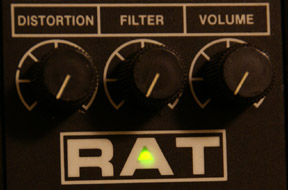
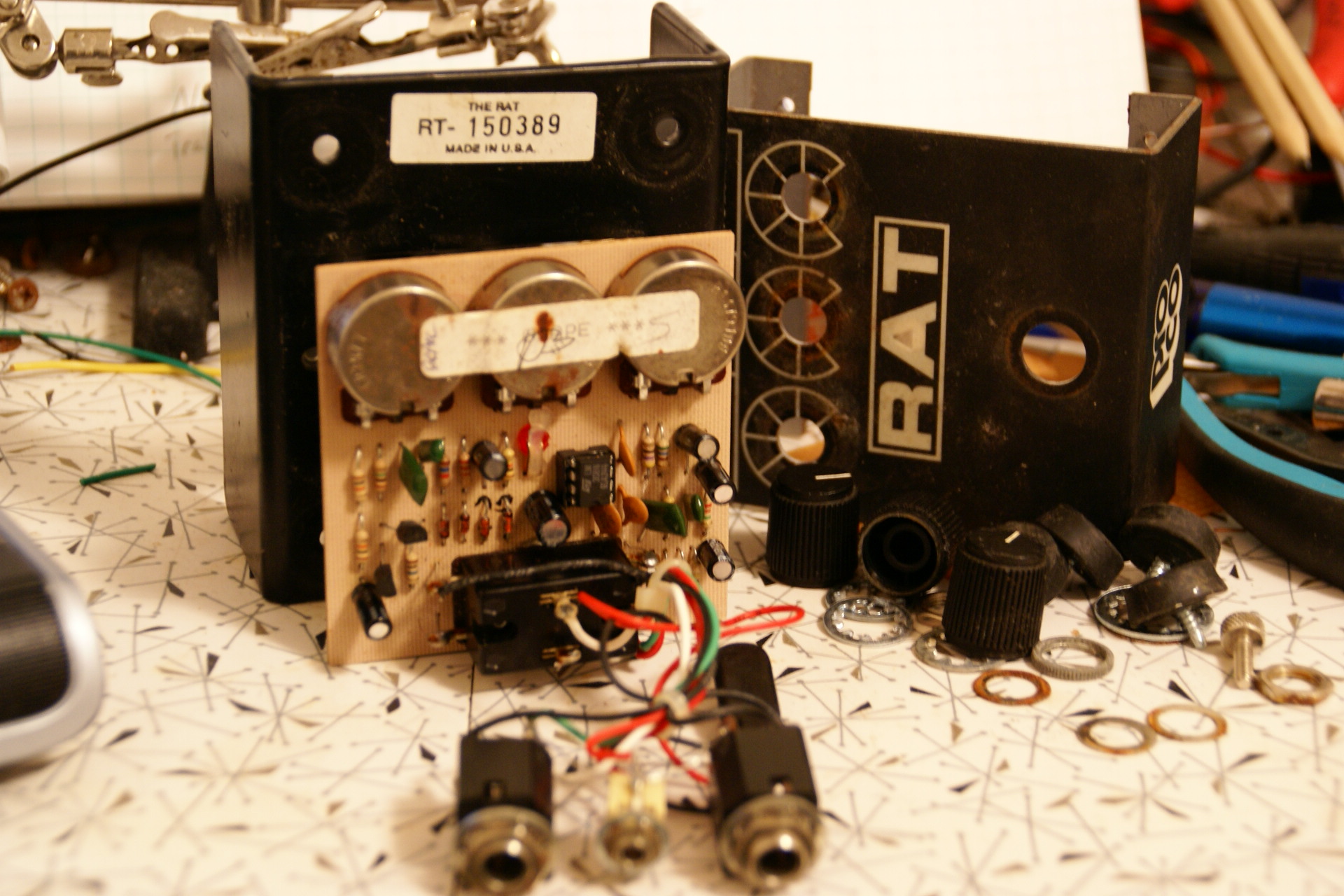
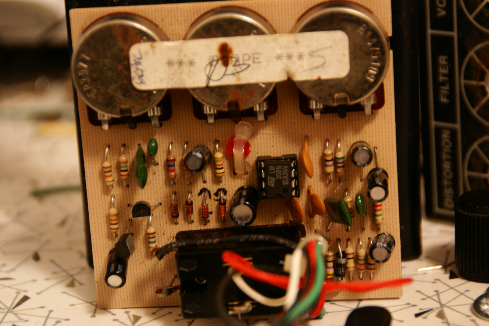
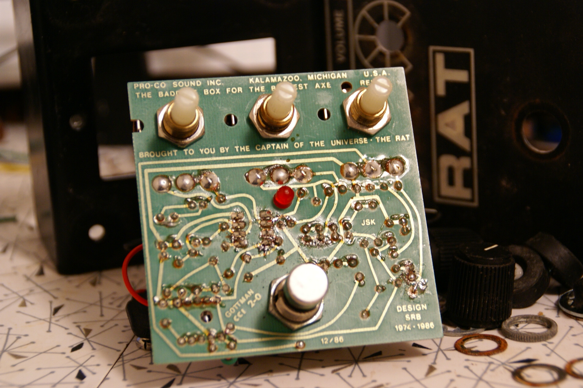
I haven't added anything here in forever. Sorry about that, but I've been focusing all my attention on my Wordpress blog. I'm not going to talk shit about Tripod on my Tripod page, but let's just say there's lots of practical reasons why I prefer to use Wordpress. But since I've noticed that alot of people still visit here via the links in my other blog, I figured it would be a good idea to do a little update here and give folks something to look at other than a bunch of gigantic pics of a ProCo Rat (I'm sure everyone's seen that stuff before anyway).

So, since this is supposed to be my Build blog, what have I been building lately? Here's the most recent; a clone of the Klon Centaur:


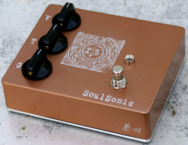
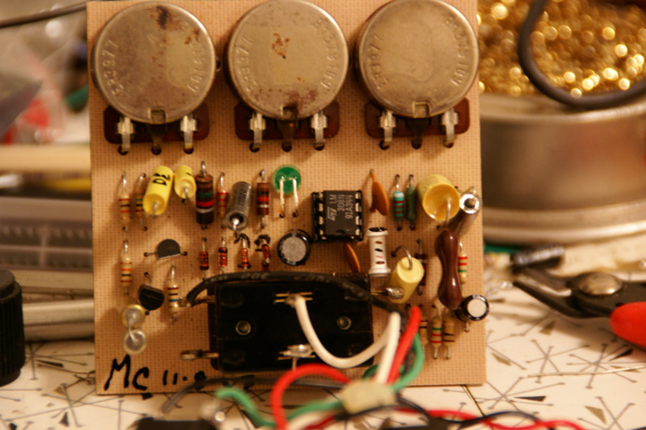
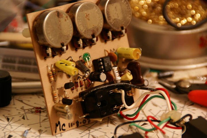
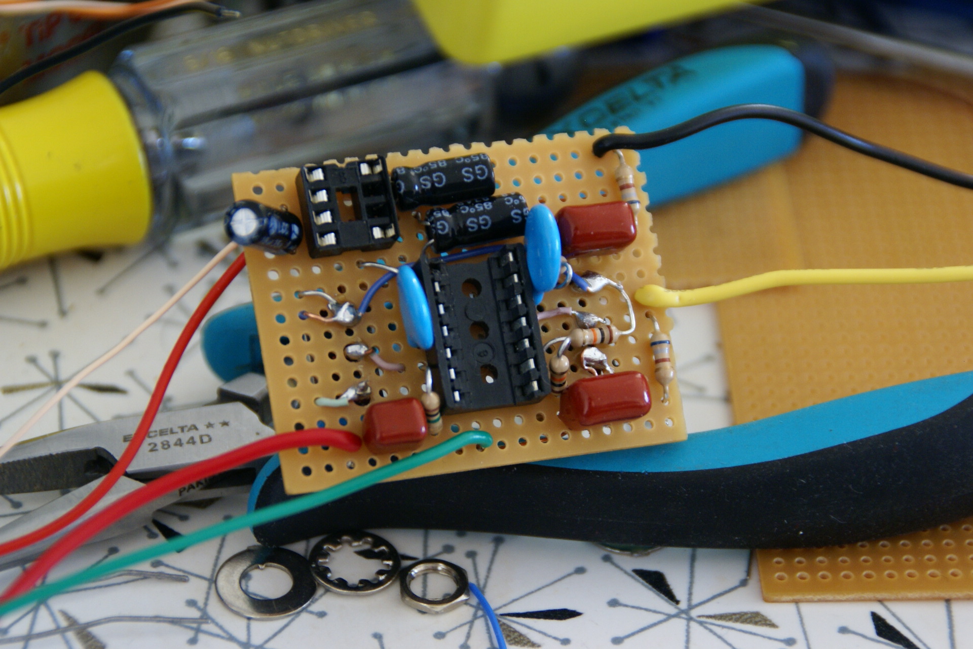
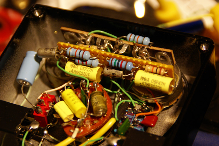
Yup, you might have seen a Klon Klone before, but this one is different - this is the first one built to verify the CORRECT schematic as traced by myself. The old Centaur schematic that had been floating around had many significant errors in it and resulted in a circuit that sounded nothing like the real thing if built. So, to put an end to the mystery once and for all, several members of the Freestompboxes community pooled money together and purchased a Centaur so that it could be de-gooped and traced. The responsibility fell onto my shoulders, and the end results can be seen here: 


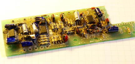
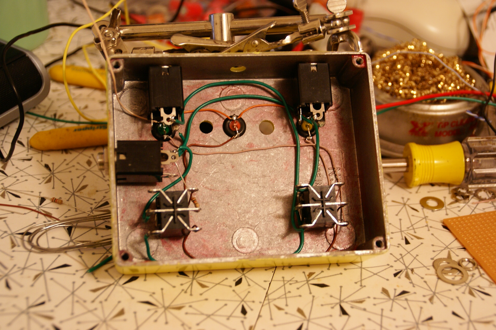
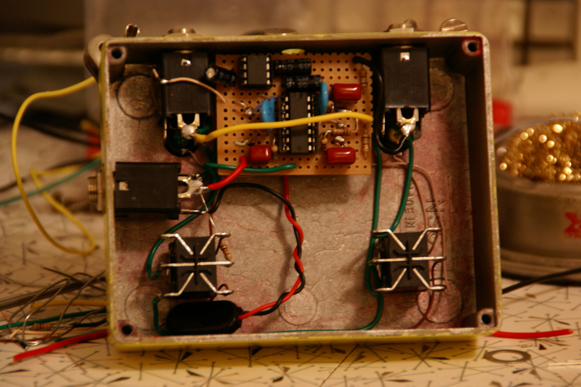
Yeah, it's pretty ugly - I still need to finish cleaning it up and re-assemble it; but at least you can see that I did indeed degoop the whole thing (bottom too, of course) and that the schematic you can find HERE is absolutely correct beyond any shadow of a doubt.

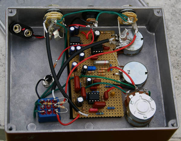
As far as details about my build are concerned; the entire thing was hand-wired on unclad perfboard, using as many of the original spec components as possible. All the small brown caps are made by Panasonic, with a couple oddball ones I threw in there (the bright blue Phillips 6n8F and old mylar 18nF...) because DigiKey was out of stock on those values when I ordered. Several of the brown caps I used are physically larger than the ones in the Klon - without realizing, I had ordered the wrong size, though the values are the same. The original used all Panasonic for the electrolytics as well, but I chose to use Nichicon bipolar caps in the signal path just out of habit (and I'm saving the Panasonic ones I bought for rebuilding the Klon). The pots I used are the usual generic Alphas and they are what they are... cheap, but reliable. The enclosure is a New Sensor 1790, purchased from Pedal Parts Plus (great folks to do business with - highly recommended!).

So, how does it sound? Well, as near as I can tell, exactly like the original. How does the original sound? I think the Klon Centaur is a very good sounding and usable overdrive, but it's not perfect. Of course, perfection is an impossible dream that has driven lesser men to madness, but still, for the amount of trouble and expense you have to go through to get one, I'd expect it would be a bit more versatile. It's not a one-trick pony; more like a two-trick pony! Ha! It does these two things really well: it has a great-sounding clean boost that very few pedals have matched, and it has a thick overdrive that works really well with certain setups and for certain types of music. Basically, that's the problem; if you want a thick heavy rock tone, the Centaur delivers, but if you want anything else you're pretty much out of luck. It doesn't do "smooth" overdrives like alot of it's present-day bootweak cousins, nor does it do a super-saturated shred distortion; but, it does work really well as a tone modifier on top of a good amp tone to push an already-crunchy amp well into the realm of some of these other tones which it cannot produce on its own. The Centaur is a pedal that becomes a part of the amplifier - adding another color to its tonal palette; an extra "more" switch that can turn a clean amp into a crunchy amp or a crunchy amp into a saturated shred amp. The trick is to know how to work the pedal/amp combination to get the desired results. People who have mastered the Centaur, consider it an essential part of their rig and would gladly pay the dear price for it. Whereas, people who are less patient, or less adroit with their equipment (or just plain want a totally different sound!) are unimpressed with the Centaur and don't "get it". Well, I get it, and I really enjoy using it.

-M.C. 

P.S.

I apologize for the sloppyness and general unreadability of this blog. Tripod's blog editor SUCKS, and no matter how much I screw around with it, I keep having the pics stuck all over the place in really bad spots that screws up any attempt at formatting. This is one of the main reasons why I hardly ever post here... sorry.


Posted by soulsonic1978 at 3:58 AM EDT
Updated: Wednesday, 25 June 2008 4:13 AM EDT
Post Comment | View Comments (10) | Permalink
Friday, 9 November 2007
Modding The Pro Co Rat2
Mood:  hug me
Now Playing: nothing....
Topic: Pro Co Rat


The SuperSonic Mod

 I spent this afternoon and part of yesterday evening modding the Rat 2 that I traced out earlier this week. I'm content an pleased with how it came out. I call it the "SuperSonic Mod" for absolutely no reason at all other than I don't think the name has been used yet....

The mod itself is a combination of component value changes which affect the function of the circuit and mojo component "upgrades". I've been collecting a lot of mojo components - carbon comp resistors, paper-in-oil caps, etc.. - so I figured I should start using them. I can't really say for sure whether using a carbon composition resistor in the circuit makes a big difference or not.... I'm not willing to take the time to make myself crazy over head-to-head comparisons of such things. All I can say is that the mod sounds very good to me, and the mod includes those components, therefore, I consider them to be an integral part of the mod.

Another interesting thing of some import is the use of high grade Tantalum caps. I've been using these really nice-looking "electrolytic" caps for lots of things for awhile now, but I was never really sure about their origins. The ones I have came in a surplus grab bag. So, I looked them up to see if it would be possible to order some more, and, lo and behold!, it turns that these "electrolytics" are actually really high grade mil-sped Tantalums. They are the Sprague 150D, and the bloody things cost about $1.80 a piece! I've always been really down on the idea of using tantalum caps for signal coupling, but these things were spec'ing so much better with my Atlas ESR meter than any electro in my possession, so I just had to give them a try. I was very pleased with how they perform in this circuit. While I'd still be wary of using any kind of tantalum in a "clean" circuit, I think they've proven themselves very useful with distortion.

Here is the schematic of the modifications:

A larger, higher resolution schematic can be found at:

http://www.aronnelson.com/gallery/d/17921-1/ProCo+Rat2+Modded+-+resized.jpg

Here are a few pics of the unit I modified. It was a little hard to cram some of the larger components in there, but it all turned out fine with no problems. I also cleaned the pots and jacks and replaced the battery clip - this Rat is getting pretty old and it's been well-loved.


So, there you can see the whole mess. See how nice those shiny Tantalum caps look? Even though I've been a tantalum hater, I can't help but love the Sprague 150D, they are great!

Yes, fancy caps, mojo carbon comp resistors in strategic places.... everything you need for a good mod..... ha!

To explain the actual mod a little bit; basically, what I did was lower the gain of the high frequencies a little bit, and then shift the cutoff point of the high frequency gain up higher. I kept the low frequency cutoff at the same point and raised the gain a tiny bit. A big change is in the compensation cap - the Rat traditionally has an oversized compensation cap which cuts the highs and causes a strange slewing distortion. I changed it to a much lower value - only 2.5pF - and the result is a much more open top end, and I was glad to hear that it can still get that signature Rat slewing distortion, it just has a different tone to it. I was able to get rid of alot of the mush - change the high frequency gain cap from 2.7uF to 470nF had alot to do with that.... having that cap value so low doesn't really do anything for the highs at all, but it overlaps too much with the 4.7uF low frequency gain cap and causes alot of low-end build up and mud. By putting the high frequency gain cap well out of the range of the low frequency one, it's much easier to set the gain for the two frequency areas independently. I really can't think of any other way to explain it The asymmetrical clipper was put in there because I like that style - I suppose you could put whatever you want, but I'm happy with what's shown in the schematic.

You can listen to an audio demo I recorded of it here:

http://www.aronnelson.com/gallery/v/soulsonic-fx/SuperSonic+Rat+Mod.mp3.html

The recording is of the modded Rat playing through a tiny little 5 watt tube amp with a 6 inch speaker. Nothing fancy, basic bedroom practice kind of thing. It was mic'd with a Heil PR-40.

If you have any questions about this mod, feel free to email me,

soulsonic1978 [at] lycos.com

Enjoy! 


Posted by soulsonic1978 at 3:53 AM EST
Post Comment | Permalink
Monday, 5 November 2007
Dissecting The Pro Co Rat
Mood:  hungry
Now Playing: Immortal - Damned In Black
Topic: Pro Co Rat

As regulars of the stompbox forums may already know, I recently traced out the schematic for my early 90's-era Pro Co Rat 2. I did this because I'm planning on modding it and I was dismayed to see that none of the schematics on the 'net matched what I had in front of me. The schematic can be found here:

http://www.aronnelson.com/gallery/d/17576-1/ProCo+Rat2.gif

Now, so people can see what I traced this schematic from, here are some gigantic up-close robot porn gutshots of the unit I traced. As far as I know, the schematic should match this exactly. A couple things to note; the IC socket is not original - I installed it years ago when I wanted to replace the opamp. The opamp in the pic is made by ST, the original was exactly the same except made by National - I still have it somewhere. I replaced the opamp because I didn't like the mushy sound it had and I thought maybe it was defective. It wasn't defective, the pedal sounded exactly the same when I put the ST one in. I now know that the mushy sound is part of the usual thing these Rats do. I plan to mod it to get rid of the mush and give it more sizzle.

Here's the stupid pics already!


Posted by soulsonic1978 at 7:27 PM EST
Post Comment | Permalink
Active Buffered A/B Box
Mood:  caffeinated
Now Playing: Black Metal Radio - Episode 144
Topic: Switchers & Buffers

How's everyone doing out there? I haven't done an update in two months... sorry about that, I guess I'd been waiting to have something interesting to put up.

 Here's an interesting little box I built for my friend Alex:


Nice, aye? It's not the cleanest work I've done, but I am pleased with how the finish came out toughness-wise. The gloss coat is Rustoleum laquer that I "baked" with a heat gun. I'm pretty much hooked on the heat gun technique now, and I'm not going to poison my oven any more by baking boxes in it. Heat gun all the way! It's so much easier to do with less guess work (you can watch it all happening as you work on it) and the fumes don't concentrate in one area like when you use an oven, and it would be easy to set up a fan for some ventalation.

But what about the inside? The circuit itself is pretty simple; a basic non-inverting buffer feeds two output buffers that have polarity reversing switches that allow them to be either inverting or noninverting amplifiers. The polarity switching circuit is a basic thing found in The Art of Electronics. The whole pedal is just some textbook circuits being powered by a application note MAX1044 power circuit.

The MAX1044 is used as a negative voltage generator to give the opamp a true bipolar supply. In the majority of cases, I always try to run an opamp from a bipolar supply whenever possible. It allows the cleanest sound with the widest dynamic range. In the case of this circuit, it can take an input level of about 8 volts before it will clip.

Here's a couple pics of the board:


I did the usual perfboard thing that I'm known to do. I mounted the switches directly to the board so it would be easier to mount it in the box. I probably agonized for an hour about how the hell I was going to mount it and still have room for the battery. Then finally, I realized it would be really easy to mount the switches to the board and build it up around them. It made a couple things about the layout a little weird, but whatever, with perfboard it's very easy to work with all three dimensions in a way that's almost impossible with PC boards.

What's with the missing socket contacts? Those were removed to make it easier for wires to pass on the wiring side of the board in a couple trouble spots. The are pins that aren't used.

Here's a couple more pics of the wiring of the footswitches and LEDs and then finally, everything together.


Posted by soulsonic1978 at 6:45 PM EST
Post Comment | Permalink
Friday, 31 August 2007
Shizzle Schematic
Mood:  chillin'
Topic: Shizzle

Okay here is the newest updated schematic for the Shizzle.

For whatever reasons my pics haven't been showing up where I stuck them in some forums. I'm wondering if I'm exceeding my bandwidth on Photobucket? Whatever... you will always be able to find the full articles and images here, so screw 'em. 


Posted by soulsonic1978 at 9:53 PM EDT
Updated: Friday, 31 August 2007 10:05 PM EDT
Post Comment | Permalink
Finished Shizzle Today
Topic: Shizzle

After much turmoil and violence, I finished a Shizzle pedal. I shouldn't have so much trouble with something that's my own design! But, I chose the hard route what with all the hand-wiring craziness...... Anyway, after all was said and done, I finally have what I would consider to be a final circuit for the Shizzle and also what I would consider my final layout.

Looksi here:


Beautiful, I know, you don't need to tell me. :wink:  Ah, if only you could hear this thing! It's very hard to describe a three-stage Germanium transistor fuzz as a smooth tube-like overdrive, but that's exactly what this thing can do! That's what makes Shizzle special, and why I have disdain for those people who thing fuzzes are put on this earth to make squealing noise.

I promise, I swear, I vow that later this weekend I will have sound samples of this thing up so you can hear what I'm talking about. I really wish I could do a video so you can watch me tweaking the knobs, but all I have available is a shitass webcam and I'm not entirely sure how I would manage recording audio and video simultaneously. My guess, is I'd probably use two machines to do it and sync them later. I say that because I want the recorded audio to be of good quality, so I'll have to do that with my desktop, but all my video ability is on my laptop..... hmmmm, yes - need to figure something out for that...

I will update this topic later later to give more info about this astonishing circuit. I know there's probably some ass out there who'll say something like "that's already been done... blah blah blah" - well, fine, if it was I didn't know about it. I came up with the idea one day when I was using my Rangemaster to boost my Fuzz Face. Then I built the thing and while I was tweaking it, I discovered all the awesome variations available, which I've never heard on another box, so whatever, I don't care how original the circuit is, I'm not trying to patent it. Nothing magical here, just a cool sound.


Posted by soulsonic1978 at 6:33 AM EDT
Updated: Friday, 31 August 2007 6:51 AM EDT
Post Comment | View Comments (2) | Permalink
Wednesday, 29 August 2007
Welcome
Mood:  not sure
Topic: Introduction

Greetings everyone in the DIY community. Welcome to The Illuminist! In this blog I'm going to try and keep track of all my builds so that others might learn from my many mistakes. I will also attempt to share as much knowledge and info as comes spilling out of my head when I tilt it too much.

These pages are dedicated to DIY Electronics - specifically circuits for musical instruments. The primary focus is going to be on pedals and amplifiers; though I might just put whatever. My goal is to try to put together something as informative and interesting as the great community of Japanese DIY blogs... there's some really great information to be found there!

 Another thing I plan on focusing on is vacuum tube circuits. I've been a fan of valve technology since I was in high school and got my first tube amp - an old Silvertone 1482; and when I got the amp it had a broken fuseholder, so my first tube amp also became my first tube project! In the approximately 14 years since that time, I've repaired, built, and modified many tube amps of all different sizes and styles. My favorite circuit to work with the the Soldano SLO100 circuit; it has been the basis for many popular high-gain amps and there's really alot to work with as far as variations on the basic theme of that circuit.

 Anyone who needs to contact me for any reason, please send email to: soulsonic1978 @ lycos.com

Thanks, and please use the information presented here, "wisely"...

-Martin Chittum 


Posted by soulsonic1978 at 3:22 PM EDT
Post Comment | Permalink

Newer | Latest | Older